Sunday, March 3, 2024

Norse Era Slide Lock and Hinges

This is a project I have been wanting to take on for a very long time. So when my  Laurel suggested I make a Viking Age lock as a project it occurred to me, why not go all out. So for this project I created an amalgam of a pressure slide lock system (I will explain firther down), replicas of the Mastermyr Box hinges and what we believe the key would have looked like as there is no physical example in the box, just conjecture, "The keyhole, now corroded, had on vertical and on horizontal slot set at right angles, It's form indicates a simple thin hooked key of a completely different type from the keys with toothed bits which are included in the find"1 The box is just a box, a man must know his limitations. 

 To start this project, I spent countless hours combing over drawing and pictures of extent slide locks of which there aer precious few; and what we do have are mostly bits and pieces which conjecture can piece back together. 


#1#2#3

In the case of the Mastermyr Box of which I am mostly copying, you can see in Images 1, 2 and 3 the front plate is missing bits and pieces, but the overall design is intact enough to make a fair guess at is was supposed to look like; amd based on the keyhole it must have been the slide lock design.  Unfortunately, we have no photos of the inside of the box, just a very un-detailed sketch (image #2), What's most interesting is that the key for the slide lock which is on the box is nowhere to be found. 

According to Göta Berg "The locks on the chest are relatively well preserved and therefore  contributes to a better understanding of the construction of this type of lock. Our knowledge hitherto has been based on similiar examples from the Birka and Vendel, but these are in a very poor state". The Mastermyr find and the Birka find mirrored each other in time frame. Birka being dated at 750AD and the Mastermyr find 795 - 1066. What is interesting is these types of slide locks would have been used up until the Middle Ages when tumbler locks were invented.

We have two other examples of slide locks in the box.(image #2). These are reverse key which would slide through a horizontal hole in the box and then pull back back to where the teeth of the key would fit into matching holes on the slide and then the slide would be pulled back against the spring allowing he slide freedom of movement. Images #4. #5 and #6 (this is a reproduction of this type of lock) 


#5#4                                                                                                                        #6

Once I decided which lock to make I started with the front plate. The Mastermyr box is quite big as you can tell from the picture and the sheer number of tools and implements which were found inside. 

#7

I chose to scale down to half scale for the sake of time and sanity. I used a piece of mild steel , 1/8" thick by 2" wide. This closely reflects what was used on the box. By 790 the Viking double bellows forges could reach temperatures as high as 1600-1800 degrees, which created a mild steel from teh introduction of carbon to the Bog iron. 
(courtesy of Lars Levin - Forges and Bellows for the VIking Blacksmith) (3)


#8

I marked out all the punch and chisel points then cold chiseled guidelines which will be visible once the steel hits the fire.  (images #9 - #11)

 #9 .#10.#11

The face plate contains 22 nails holes which I hand punched using a square punch i made myself for just such usage. (images #12-#15)

#12 #13#14

#15
Once I finished the Nail holes, I move to the holes for the supporting rings that will hold the slide in place. and then hot cut the key holes and the slots for the hinge loops. (images #16 - #19)

#16 #17 
#18 #19

Once that was done, I made the Mastermyr hinges with the latch loops (image #20-#22). I mounted the the plate onto a scrap piece of wood to enable a correct depth for the loops so the will lock into the slide rod. (image #23)

#20 #21

#22 #23

The last piece of the front plate puzzl;e was the interior lock rings which hold the rod snugly in place so it can slide smoothly (image #24) 

#24
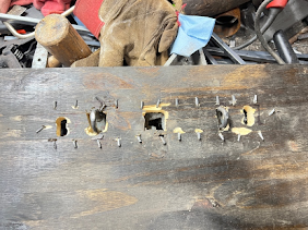
Once I mad the locking rings and riveted them to the ends of the front plate, I cut our teh facia board and cut in the holes. Everything lined up as you can see in image #24, but in my haste to secure the lock plate, i forgot to drill pilot holes in the wood and cracked it with the nails.  (image #25) sending me back to cut out another  facia board.

#25

The next part was the most difficult and time consuming. Making the slide rof. This needed to several things at once. The process required heating and bending and refitting and then heating and re-bending it until:
1) The hook on the far end catches the left latch loop (images #26 and #27

2) The center, where I flattened the round bar to accept the square key, is in a place that will allow it to slide closed (image #28) 

3) The right end to slide through the latch on the right side. It took several little adjustments with the and without the latches in the holes. (image #29) 


#26 #27
#28 #29

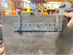
The last part of slide system is a pressure plate that rides above the rod and keeps it tight and in place. I forged that out of mild steel and hand made the rivets to hold it in place (Image #39) Showing here the same Mastermyr diagram of the lock (image #31)


#30

#31
Once the slide was in place and everything worked all that was left to do was make the back hinges, the key, and treat all the metal work with beeswax to preserve it. 

Once the box was constructed all the little quirks and eyeball measurements are brought to light. The two latch hinges were not quite the same length so it was necessary to recess the shorter one slightly into the box lid to make it fit correctly. This is very much how something would have been built in period  when everything is a one off, and you make things to fit. 

One thing you may notice is that all the nails are turned down instead of being clipped . The Norse builders all did this a practice to ensure whatever was being nailed down stayed down. They applied this practice to boat building as well. In the Mastermy booklet it is noted "Only eight if the original twenty remain. The nails are turned over on the inside of the wooden panel"(5)
***THE BOX IS JUST A VEHICLE FOR THE METAL WORK - IT'S NOT PART OF THE PROJECT ****

#32 #33
#34 #35
#36

*** THE KEYHOLE IS FAIRLY RECESSED SO SHINING A LIGHT ON THE SUBJECT WILL MAKE IT EASIER TO FIND***

To sum up this project I can say that to start, this kind of precise metal work is way out of my confort zone which is exactly what Master Estgar wanted me to do on this project. I spent more time thinking about  and looking at examples of Norse slide locks (what few images there were) then I do when making something that is already ingrained in my skill set. 

I did several thumbnail drawings just to figure out how this thing should go together without one full example to look at The specific historical period and some educated guesses led me to the path of creating a version of the Mastermyr box which absolutely existed, asthe pieces of said locks were in the box. I could have done a replica of the box itself, but I wanted to make a working version of the this type of lock, so it was important for me to pull together period aspects of different known locks.  Except for using a propane forge, all the materials, tools and methods were done in a period fashion. 
Historians believe the box might have been used for something else before it began to deteriorate and become relegated to a toolbox.

I truly enjoyed being challenge on this project and while at times pieces of this box really wanted to take flight across the shop, I remained calm, took a step out of the shop and returned wih vigor to congquer the steel and force it to succumb to my will. The result being what I believe to be a fair representation of a working version of the Mastermyr Box.


  • 1 The Mastermyr Find - a Viking Age Tool Chest from Gotland  - by Greta Arwidson and Gösta Berg - Skip Jack Press 1999 PAge 8
  • 2 Images #6 Viking lock examples  - Lodin's Locks -  http://www.fjelborg.org/lodinsvikinglocks.htm 
  • 3 Image #11 Lars Levin Forge and Bellows for the Viking Blacksmith http://levincraftsmanship.wordpress.com/2017/06/11/viking-forge-bellow/
  • 4 Images #31 Mastermyr pages 8, Figure 2
  • 5 Mastermy page 7 
  •  


Tuesday, August 15, 2023

15th Century Cabinet Hinge

                                                     15th Century Hinge Project

Lord Brandr Aronsson


This is a project I have wanted to tackle for quite some time, but I never had the time to devote to it. This is a 15th century Oak cupboard from either the Netherlands or France and it currently resides in the Metropolitan Museum of Art’s Cloisters Collection. I have been fascinated by the hand forged hinges on this piece for years. It is a multi-piece project. First you have cross hinges which make up the center hinge on each door.  Second will be the decorative arms on top and bottom of each door, which I believe has a whole story of its own, but we will get into that for part two of the project. 


The center crossed hinge are made up two 2” x 3 1/16” (roughly) of flat mild steel. Mild steel is iron with just enough carbon to be able to form shapes without splintering like wrought iron but not enough carbon to hold an edge for a blade.


I spent a lot of time trying to figure out the process of just how the Master Smith who created these did it. 


My first attempts which seemed sound at the time ended in epic failures. My first thought was that he drew out both ends and created the hook before doing anything else. Then I thought he bent it in on itself and created the curves after that. So, I attempted that. 


I did not get quite the result I had seen in my head.  


Next, I thought of different technique where you draw out the ends like the first attempt but instead of trying to fold sideways, fold it over on itself, then use the hammer and heat to flatten it into place, then curve the arms. 

Here is the result of that. 


Epic fail number two. By this point I was getting rather frustrated at what in my mind should have been time consuming but ultimately doable project. 


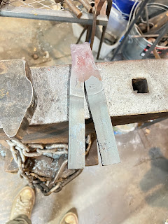
So, I took a breather and sat back down and looked at my myriad of photos of the hinges. Then the light bulb over my head went off. Sometimes the most obvious and easiest solution is the answer when you stop and think. So I took a ten-inch piece of 3/16”  x 2” flat stock and made a six inch cut with a hack saw down the middle of the piece leaving four inches for the flat and the hinge, and voila that is how they did it. 

The first thing I did was to fuller the hinge end (Fullering is the process of expanding and shrinking the metal at the same time) to create the right size mass for the hinge, which will be hot rolled around the hinge pin for a perfect fit. 


Once the tail end was the width and length I wanted. I turned it around and started working each of the arms down to the right size point and then creating the curved end.


Once the curved ends were formed, then came the hard part. Due to the thickness of the material, creating the recurve took some muscling and coercing of the steel, but eventually I made it obey my will, (there was some colorful language involved) and the recurve was formed. 


Making these types of curves on flat stock is not as easy as it seems, as the steel really does not want to bend that way. So, there is a technique for fooling the steel. You heat the metal and hit the opposite direction almost folding it in half. Once that is done you heat it again and then using the anvil you flatten the bend and that gives you most of your curve. This takes a number of heats as you have to deal with the excess steel that builds up around the curve as seen in the previous failed attempt. However, the technique worked just fine here and I got both halves of the hinge drawn out, and cleaned up with a hot rasp. 


The next step was to create the actual hinge. Hinge making is a basic blacksmithing skill which is something all blacksmiths learn early on. The hinge design on this project is a standard slip pin hinge. 


The process involves heating the flat (and hopefully you have given yourself enough room to create the hinge roll.) You start with the face of the hinge facing down so that as you hammer down and across the steel you are creating a cup that will be facing up once you flip the piece and then that creates your hinge roll. 


Once you have created matching rolls on each half of the hinge, you mark it for cutting. One side will have a center loop and the other side will have a space. It’s always a good idea to leave a little more room in the space so the hinge can swing freely.

Using a hack saw, I hot cut the pieces. Cutting away for the center loop is easy.  Cutting away the center is a little more involved. You have to cut your slits then heat it up and using a hammer and chisel hammer the center piece out of place to ninety degrees. Then you can use the saw to cut off the excess. 


Once that is done, you can fit the to halves together. You might need to do a little adjusting. With these it was just a little tight. So I put the split back into the forge and heated it up.


Using a wooden mallet so as not to deform the metal, I tapped it into place, and it made a perfect fit. 

The next thing to do was to drill the holes for the nails and forge a pin for the hinge. 


The last thing to do before mounting the bracket was to treat the entire piece with beeswax to keep it sealed. 


This project was a lot of fun. It was also quite challenging at times, and I had to utilize some new techniques to create the final piece. Considering that a hinge in general is a fairly utilitarian object, its amazing how much we rely on them Without hinges,  doors don’t open, trunks don’t open and shutters don’t open. Decorative hinges are a luxury and these particular ones were most definitely custom work from the local blacksmith. 


The next part of the project will be the upper hinge and arm support. 


What I find most intriguing about this part of the set is that after many hours of scrutiny it is clear to me that the three sections of the design were added over time with the different sections having been brazed onto the existing piece.


However, that is for another time.


Provenance – The Metropolitan Museum of Art, Cloisters Collection

Bequest of Susan Vanderpool Clark 1967 (67.155.9)


Norse Era Slide Lock and Hinges This is a project I have been wanting to take on for a very long time. So when my  Laurel suggested I make a...